Automotive Penetration Testing
Welcome to the first of many blog posts in the world of car penetration testing! As vehicles continue to integrate electronic systems, software, and network connectivity, they become vulnerable to malicious attacks.
Car penetration testing is a cybersecurity field that focuses on identifying security weaknesses in automotive systems. By exploring the vulnerabilities found in modern cars, we can better understand the risks associated with their digital infrastructure and work towards establishing robust defenses.
The Roadmap Ahead: Exploring Car Penetration Testing Topics
In this blog post series, we’ll cover various fascinating topics related to car penetration testing. Here’s a sneak peek at what lies ahead:
Exploring the Inner Workings of the Controller Area Network (CAN) Bus Protocol: In this post (the one you’re reading!), we’ll dive deep into the CAN Bus Protocol, the backbone of communication in modern vehicles. Understanding how this protocol works is crucial for unraveling the vulnerabilities that exist within the network.
Setting Up can-utils to Connect to CAN Devices: Once we have a solid understanding of the CAN Bus Protocol, we’ll explore how to set up and utilize the powerful can-utils tool. This tool will enable us to connect to CAN devices, monitor the network, and analyze the data flowing through it.
Unraveling the Process of Reverse Engineering the CAN Bus: Reverse engineering is a key skill in car penetration testing. In this post, we’ll delve into the fascinating world of reverse engineering the CAN Bus, where we’ll learn how to analyze and understand the data exchanged between different components in a vehicle.
Venturing Into the Realm of ECU Hacking: Electronic Control Units (ECUs) are the brains behind various vehicle systems. In this post, we’ll explore the vulnerabilities that exist within ECUs and how to exploit them for hacking purposes. We’ll uncover techniques to gain control over these crucial components and potentially manipulate their behavior.
Through this exploration, my aim is to share practical knowledge about automotive cybersecurity. By the end of this series, you’ll have a solid foundation in car penetration testing, enabling you to identify vulnerabilities, understand potential attack vectors, and contribute to the ongoing efforts to secure vehicles in the digital age.
Understanding Vehicle Bus Protocols
Vehicle bus protocols govern the transfer of packets within a vehicle’s network, enabling communication among sensors and controlling information flow and behavior. Each vehicle manufacturer selects suitable bus protocols tailored to their vehicles.
While the CAN bus is a standardized protocol found on the OBD-II connector of all vehicles, the packets transmitted over the CAN bus itself are not standardized. To identify specific bus lines for your vehicle, you can refer to its OBD-II pinout available online.
In this blog post, we’ll provide an overview of various bus systems and protocols you may encounter in your vehicle, but we’ll focus primarily on the CAN Bus Protocol.
Understanding the CAN Bus Protocol
The Controller Area Network (CAN) is a vital protocol used in the manufacturing and automotive industry to facilitate communication between embedded systems and electronic control units (ECUs) in modern vehicles. While CAN has been a standard on US cars and light trucks since 1996, it only became mandatory in 2008 (2001 for European vehicles). If your car predates 1996, it may still have CAN, but verification is necessary.
CAN operates using two wires known as CAN high (CANH) and CAN low (CANL). It employs a technique called differential signaling, where a signal increases the voltage on one wire while simultaneously decreasing it by the same amount on the other wire. This approach is crucial in environments that require noise tolerance, such as automotive systems and manufacturing.
Understanding CAN Bus Packet Layout
The CAN bus utilizes two types of packets: standard and extended. Extended packets provide a larger space for holding IDs compared to standard packets.
Standard Packets
Standard CAN bus packets consist of four essential elements:
- Arbitration ID: This ID identifies the device attempting to communicate. In case of simultaneous transmission, the device with the lower ID takes precedence.
- Identifier Extension (IDE): This bit is always set to 0 for standard CAN.
- Data Length Code (DLC): The DLC represents the size of the data, ranging from 0 to 8 bytes.
- Data: This field carries the actual data. The maximum size of the data in a standard CAN bus packet can be up to 8 bytes. However, some systems enforce 8 bytes by padding out the packet.
Since CAN bus packets are broadcasted, all controllers on the network receive them, similar to UDP on Ethernet networks. These packets do not include information about the sender, allowing any device on the bus to easily simulate another device.
Extended Packets
Extended packets can be linked together to create longer IDs while maintaining backward compatibility. They fit within the standard CAN formatting, ensuring compatibility with devices that do not support extended packets. Extended packets use Substitute Remote Request (SRR) instead of Remote Transmission Request (RTR). The IDE is set to 1, and they feature an 18-bit identifier as the second part of the standard 11-bit identifier.
In addition to extended CAN, some manufacturers use their own CAN-style protocols that are also backward compatible with standard CAN.
The Advantages of the CAN Protocol
The CAN protocol has addressed several challenges that existed before its implementation, including the complexity of wiring structures, the difficulty of adding or removing components, and the presence of multiple wires connecting different Electronic Control Unit (ECU) nodes.
Electronic Control Units (ECUs) are embedded systems or computers within a vehicle that control and manage various electrical and electronic functions. ECU nodes are responsible for monitoring and controlling different systems and components in a vehicle, such as engine management, transmission, braking, airbags, climate control, and more. Each ECU node specializes in a specific function and communicates with other ECUs to ensure coordinated operation and efficient performance of the vehicle.
Exploring the Features of the CAN Protocol
Now, let’s take a closer look at the features that make the CAN protocol remarkable:
Easy Addition and Removal of Nodes: The CAN protocol allows for effortless addition and removal of components, known as nodes, within the network. These nodes can represent various components like power windows, power locks, and engine control. This flexibility enables efficient maintenance, upgrades, and customization of the vehicle’s electronic systems. Adding or removing a node can be done without disrupting the functionality of other nodes.
Independent Operation: In a CAN network, each node operates independently, connected to the communication lines. This means that nodes can transmit and receive packets over the CAN High (CANH) and CAN Low (CANL) lines, enabling them to exchange information and perform their specific functions without relying on a central controller.
Broadcast Communication: CAN is a broadcast-type protocol, granting all nodes access to the CANH and CANL lines. This facilitates efficient and simultaneous communication between multiple nodes. Each node can transmit messages that are received by all other nodes on the network. This broadcast communication enables real-time data sharing and coordination between different components.
Message-Based Protocol: CAN operates as a message-based protocol, where each message is assigned a unique identifier. Messages serve as the units of communication within the network and carry specific information related to the node’s operation or the vehicle’s functionality. The unique identifiers help identify and distinguish different messages on the CAN network, ensuring accurate and targeted communication between nodes.
Serial Asynchronous Protocol: CAN is a serial protocol, transmitting data sequentially, bit by bit. It follows an asynchronous communication scheme, where nodes do not require synchronized timing for transmission and reception. This asynchronous nature allows for flexible and efficient communication, especially in situations where nodes may have varying processing speeds or delays.
Overall, the CAN protocol provides a robust framework for interconnecting nodes in a vehicle’s network. Its features enable easy integration, independent operation, efficient broadcast communication, and reliable message-based interaction between nodes. These capabilities make CAN a widely adopted and effective protocol for automotive systems, offering flexibility, scalability, and resilience.
Implementing the CAN Protocol
The implementation of the CAN protocol is not only fascinating but also crucial for ensuring the smooth operation of a vehicle’s communication system. In a CAN network, multiple nodes collaborate to transmit data over the CAN bus, acting as small computers within the vehicle. Each node is equipped with an Electronic Control Unit (ECU), serving as the brain that controls its specific functions and facilitates data transmission on the CAN bus.
One intriguing aspect of the CAN protocol is that every node possesses the capability to both read and write data on the bus. However, before a node can send its data, it politely checks if the bus is currently engaged in other transmissions. This process, known as bus arbitration, is akin to patiently waiting for one’s turn to speak in a group conversation. Once the node determines that the bus is available, it proceeds to transmit its data, which can then be received by other nodes.
By granting each node the opportunity to access the bus and send data when it’s free, the CAN protocol ensures efficient communication without conflicts. This mechanism resembles a well-organized discussion where everyone has a chance to speak and share information.
In simpler terms, the CAN protocol enables different components of a vehicle to communicate with each other by sending messages over the CAN bus. Each component has its own ECU, acting as a small computer that controls its functions and facilitates data exchange. These components take turns sending their data, facilitating smooth information sharing and effective collaboration. It operates as a teamwork mechanism, enabling the vehicle’s systems to communicate and operate seamlessly.
CAN Data Frame Architecture
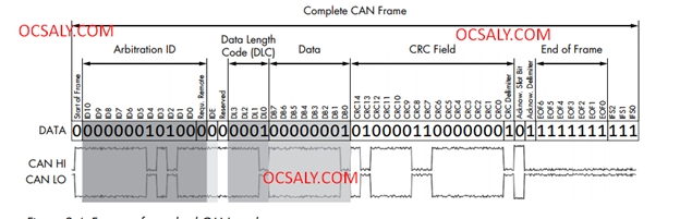
The CAN Data Frame Architecture establishes a standardized structure for transmitting data over a Controller Area Network (CAN) network, ensuring consistent and reliable data transmission among network nodes. Let’s explore the components of the CAN Data Frame to gain a better understanding of their functionality.
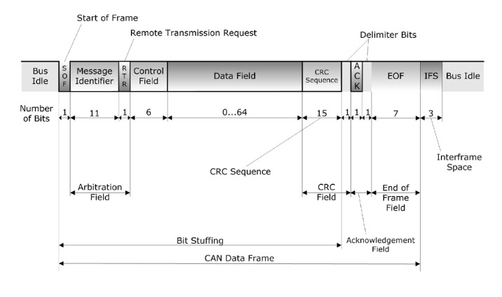
Bus Idle: This state indicates that no data transmission is currently ongoing on the network. During this period, the CAN bus is available for communication, and the bit value is set to one.
Start of Frame (SOF): The SOF bit is consistently set to zero and serves as a signal to other nodes, indicating the commencement of a data transmission. It functions as a synchronization mechanism, preparing nodes to receive the upcoming data.
Arbitration Field: The Arbitration Field contains the Message Identifier (Message ID) and the Remote Transmission Request (RTR) bit. The Message ID is a unique identifier that determines the priority and content of the message being transmitted. Meanwhile, the RTR bit differentiates between data frames and remote frames, the latter of which are utilized for requesting data from other nodes.
Data Field: The Data Field is where the actual data is stored and can hold up to eight bytes of information. It serves as the container for the payload of the message being transmitted.
CRC Field: The CRC Field (Cyclic Redundancy Check) represents a checksum that ensures the integrity of the transmitted data. Both the sender and the receiver calculate the CRC, and if they match, it indicates that the data transmission was successful without any errors or corruption.
End of Frame (EOF): The EOF bit signifies the conclusion of the data or remote frame transmission. It denotes the completion of the data transmission process.
Understanding the CAN Data Frame Architecture is vital for facilitating reliable and efficient data transmission within a CAN network. By adhering to this standardized architecture, the CAN protocol enables consistent communication between nodes. Each component within the data frame serves a specific purpose in the transmission process, including synchronization, identification, data storage, error checking, and acknowledgement. Through this standardized architecture, the CAN protocol enables seamless communication and coordination among the various components of a vehicle’s communication system.
Nodes in the CAN Protocol
To gain a better understanding of the CAN protocol, it’s essential to delve into the concept of nodes. In the context of the CAN protocol, a node refers to each component connected to the CAN network, and each node has its own unique role and responsibilities. Let’s explore nodes in more detail.
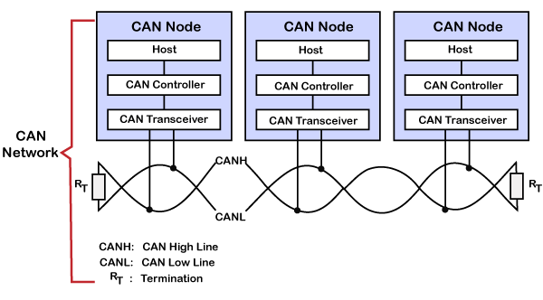
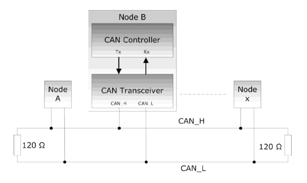
In a CAN network, all the components are interconnected by two lines: CAN High and CAN Low. These lines serve as the communication channels within the network, and all the nodes are connected to them. Each component, whether it’s a sensor, actuator, or controller, is considered a node in the CAN network.
A node consists of three main components: the host, controller, and transceiver. Let’s discuss each component in detail.
Host: The host is responsible for controlling the functionality of the node. It can be either a microcontroller or a microprocessor, depending on the complexity and specific tasks the node needs to perform. Think of the host as the brain of the node, making decisions and overseeing the overall behavior. It determines which messages to send and when to send them.
Controller: The CAN controller is in charge of communication on the CAN network. It handles the transmission and reception of messages. When a message intended for a specific node is received, the controller generates an interrupt to alert the host. For example, if a message related to power windows is received, the CAN controller generates an interrupt and forwards the message to the host responsible for controlling the power windows.
Transceiver: The transceiver handles the physical transmission of CAN packets. It receives and sends messages on the CAN network. The controller checks each incoming message to determine if it is intended for the specific node. If the message is relevant, an interrupt is generated, and the message is sent to the host. The transceiver plays a vital role in ensuring reliable communication between nodes.
In summary, a node in the CAN protocol comprises the host, controller, and transceiver. The host controls the node’s functionality and makes decisions regarding message transmission. The controller manages communication on the CAN network and generates interrupts for the host when relevant messages are received. The transceiver handles the physical transmission of packets, ensuring reliable communication. Together, these components work in harmony to enable efficient and effective communication within the CAN network.
Understanding Data Transmission and Arbitration on the CAN Bus
Let’s explore how data is transmitted on the CAN bus and how nodes determine access to the bus when multiple nodes want to send data simultaneously.
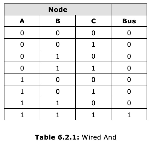
To begin, it’s important to understand how zeros and ones are represented on the CAN bus. In the CAN protocol, a logic one is referred to as the “resistive state,” while a logic zero is known as the “dominant state.” The resistive state represents a one, while the dominant state represents a zero.
During periods of no communication on the bus, the idle state is always set to the resistive state (one). This is similar to other protocols such as synchronous serial protocols. The voltage level during the resistive state is typically around 2.5 volts.
To transmit a zero on the CAN bus, the CAN high line is pulled up to 3.5 volts, while the CAN low line is pulled down to 1.5 volts. This creates a dominant state, which overrides the resistive state. Once a node sets the state to dominant, it cannot be changed back to the resistive state by another node. Hence, the dominant state always takes priority over the resistive state.
Now, let’s consider a scenario where multiple nodes want to send data on the bus simultaneously. In the CAN protocol, the priority of messages is determined by the message identifier, which is defined in the arbitration field. Each node has a unique identifier, represented by an 11-bit value in hexadecimal or binary format.
To determine which node gains access to the bus, let’s consider an example involving three nodes: Node 1, Node 2, and Node 3. All three nodes attempt to send data on the bus simultaneously. We can visualize this scenario on a graph, with the most significant bit (MSB) considered first.
If all three nodes set the MSB to one, the bus remains in the resistive state since all nodes are in agreement. Consequently, the bus continues to be in the resistive state. The same applies to the second bit.
However, when we reach the third bit, Node 3 transmits a zero (dominant state), while Nodes 1 and 2 transmit ones (resistive state). In this case, the dominant state overrides the resistive state, causing the bus to switch to the dominant state. As a result, Node 3 wins the arbitration and gains access to the bus. Nodes 1 and 2 will no longer transmit any further bits on the bus.
Once a node wins the arbitration, it begins transmitting its data on the bus. Initially, it sends the identifier packets, followed by the message packets.
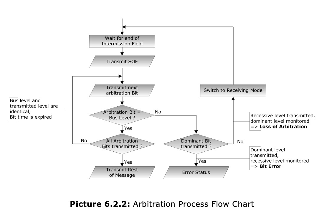
It’s important to note that the CAN bus operates on wire and logic rules. If any node sets the bus to a dominant state (zero), no other node can change it back to a resistive state (one) until all nodes agree to be in the resistive state. The bus status will only become one when all three nodes transmit a one in the last bit.
In conclusion, data transmission on the CAN bus involves utilizing resistive and dominant states. Nodes compete for access to the bus based on their message identifiers, with the node possessing the highest-priority identifier winning the arbitration. This process ensures orderly communication on the bus, and the bus status is controlled by wire and logic rules.
Understanding CAN Data Frames and Remote Frames
In the CAN protocol, it’s important to distinguish between CAN data frames and CAN remote frames as they serve different purposes. Let’s explore the characteristics and differences of these two frame types.
A CAN data frame is responsible for carrying actual data and facilitating information exchange between nodes on the CAN bus. It encapsulates various types of data, such as power window status, temperature readings, or other relevant information. The data frame comprises a data field that stores this information.
On the other hand, a CAN remote frame does not contain a data field. Its primary function is to request specific data from other nodes. It’s analogous to raising a hand and asking for information. The remote frame acts as an initiation for communication, indicating a desire for certain data.
To illustrate this distinction, let’s consider an example where an air conditioning node in a car wants to inquire about the status of the power windows. To obtain this information, the air conditioning node generates a dedicated request frame for the power windows. This request frame is then transmitted across the CAN bus.
Upon receiving the request frame, the power windows node recognizes that the air conditioning node is seeking information about the power windows. As a response, the power windows node generates a data frame containing the relevant data, such as the current state of the windows (open or closed). This data frame is transmitted on the CAN bus, received by the air conditioning node, and fulfills its request.
In summary, the key distinction between a CAN data frame and a CAN remote frame lies in their purposes. While a data frame carries actual data exchanged between nodes, a remote frame serves as a request for data. Additionally, there is a difference in the value of the arbitration field between the two frame types. In a data frame, the arbitration field is dominant (zero), whereas in a remote frame, it is recessive (one).
The OBD-II Connector
Most vehicles are equipped with an OBD-II connector, also known as the diagnostic link connector (DLC), which connects to the internal network of the vehicle. These connectors are typically located under the steering column or discreetly placed on the dashboard. They may be concealed behind access panels and can be either black or white in color. While some OBD-II connectors are easily accessible, others may be tucked away under plastic covers.
Conclusion
In conclusion, the CAN Bus Protocol is a vital communication protocol in modern vehicles that enables seamless interaction between different components. By utilizing a message-based approach and standardized data frames, the CAN protocol ensures reliable and efficient data transmission. With its features of easy node addition and removal, independent operation, broadcast communication, and message-based interaction, the CAN protocol offers flexibility, scalability, and resilience. Understanding the CAN Bus Protocol is essential for automotive penetration testers to identify vulnerabilities, analyze network behavior, and contribute to securing vehicles in the digital age.